
 Welding Resources Welding Symbols
Welding Symbols
Special symbols are used on a drawing to identify where welds are to be located, the type of welding joint to be used, as well as the symbol size and amount of weld metal to be deposited in the joint. These welding symbols have been stan¬dardized by the American Welding Society. You will come into get in touch with these welding symbols anytime you do a welding job from a set of blueprints. You desire to have a good working knowledge of the basic weld symbols and the regular location of all the elements of a welding symbol.
A regular welding symbol (fig. 1-11) consists of a reference line, an arrow, and a tail. The reference line could be the foundation of the welding symbol. It is used to apply weld symbols, dimensions, and other type of data to the weld. Simply the arrow connects the reference line to the welding joint or area to be welded. The direction of the arrow has no attitude on the significance of the reference line. The conclusion of the welding symbol is used only when necessary to include a specification, process, or other reference welding information.
Weld Symbols
The term welding symbol refers to the symbol for a specific type of welding. As discussed earlier, Tig Welders,Mig Welders,Ac Dc Welding and are all types of welds. Basic weld symbols are shown in figure 1-11

Figure: 1.11 Basic weld symbols

Figure: 1.12 Weld symbols applied to reference line.

Figure: 1.13 Specifying weld locations.
Symbol is only part of the information required in the welding symbol. The term welding symbol refers to the full amount of symbol, which includes all information needed to specify the weld(s) required.
Figure 1.11 shows how a weld symbol is applied to the reference line. Notice that the vertical leg of the weld symbol is shown drawn to the left of the slanted leg. Regardless of whether the symbol is for a fillet, bevel, J-groove, or flare-bevel weld, the vertical leg is always drawn to the left.
Figure 1.12 shows the significance of the positions of the weld symbols position on the reference line. In view A the weld symbol is on the lower side of the reference line that is termed the arrow side. View B shows a weld symbol on the upper side of the reference line that is termed the other side. When weld symbols are placed on both sides of the reference line, welds must be made on both sides of the joint (view C).
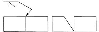
When only one edge of a joint is to be beveled, it is necessary to show which member is to be beveled. When such a joint is specified, the arrow of the welding symbol points with a definite break toward the member to be beveled. This is shown in Figure 1.13.